TM-5-4310-389-14
17.
Turn the crankshaft through 360 degrees int he direction of engine rotation. Undo the cylinder head and remove
the piece of lead wire. Measure the thinnest part of the squeezed wire. For piston crown clearances, see
specifications table 4-2.
NOTE
This is the easiest method of getting the correct clearance; if the clearance is too small, remove the
cylinder and place the number of shims required below the cylinder or if the clearance is too large,
raise the cylinder, cut through the surplus shims with side-cutting pliers, and remove.
18.
Adjust clearance by shims: 0.008-inch (0.2 mm), 0.020-inch (0.5 mm), 0.032-inch (0.8 mm), or 0.039-inch (1.0
mm) are available. Keep the number of shims in the stack to an absolute minimum.
19.
Reinstall the cylinder head. Refer to 4-11 and Appendix F.
20.
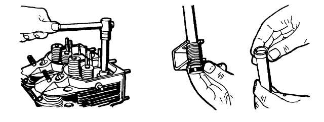
Screw plugs into cylinder heads fitted with new gaskets into the holes for the cylinder head studs (use socket
spanner No.003-0512 and square socket insert No.44 003-0511, figure 5-44).
21.
Assemble and tension the spring by turning (use spring compressor tool No. 003-0501, figure 5-45, left).
22.
Install the flat washer with the domed side facing towards the spring. Fit a new sealing ring with the flat side
facing towards the end of the push rod tube (figure 5-45, left).
23.
At the opposite end of the tube, fit a new sealing ring with the fault side facing towards the shoulder (figure 5-45,
right).
Figure 5-44. Fitting Screw Plugs into
Figure 5-45. Assembling Push Rod
Cylinder Head
Assemblies
5-27