TM-5-4310-389-14
8.
Oil the crankpin. Place the connecting rod bearing on the crankpin (figure 5-42).
CAUTION
When rotating the crankshaft, ensure the cylinders do not lift from the contact surface.
9.
Assemble the mating cap on the connecting rod bearing. Install new connection rod bolts; tighten and lock down
in accordance with Appendix F (use angle-of-turn indicator No. 003-1102).
10.
Check rod bearing to crankshaft journal side clearance (table 4-3). Bring the cylinders into alignment.
11.
Position the engine right side up.
12.
Coat with grease a piece of 0.079-inch (2 mm) gauge lead wire and stick it at right angles to the center line of the
engine on the piston crown.
13.
Mount the cylinder head. Measure the length of the cylinder head studs.
14.
Renew those cylinder head studs that have stretched beyond the limits stated in the specifications (table F-1 of
the appendix).
15.
Assemble the studs fitted with washers and slightly tighten. Bring the inlet and exhaust flanges of the cylinder
heads into alignment; ensure that in doing so the cylinders do not get out of alignment.
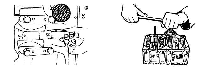
16.
Torque bolts to 30 Nm (see tightening procedure, table F-1 of the appendix) and tighten through one stage (45
degrees) with the aid of device No. 003-0500 (figure 5-43).
Figure 5-42. Positioning Big End Bearing
Figure 5-43. Preloading Cylinder
Bearing on Crankpin
Head Bolts
5-26