TM-5-4310-389-14
3.
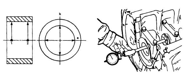
Measure each main bearing bore at points 1 and 2 plane a, then in the same manner in plane b offset by 90
degrees, in order to determine any contraction, out-of-roundness, or conicity (figure 5-60).
4.
If the recorded values correspond to those specified in table 4-5, the respective bearing bore is in an
acceptable condition and the required preload will be obtained when new bearing shells are installed.
5.
If the threaded bearing bore diameters differ only slightly from the specified values listed in table 4-5, repeat
the measurements with the new bearing shells installed.
6.
Insert new bearing shells, mount bearing cap, then preload and tighten up according to instructions.
7.
Gauge each bore at points 1 and 2 in the vertical and horizontal positions a and b (figures 5-60 and 5-61).
8.
If the recordings show that the bearing tolerances are up to 0.0008-inch (0.020 mm) maximum above the
values specified in table 4-5, the crankcase is acceptable for further use. Otherwise, it is necessary for the
line of bearing housings to be reworked to an oversize outside diameter on a line boring machine. It is not
permissible to bore out individual bearing pedestals. Nor is it permissible to restore the required preload by
underlying the bearing shells or by reworking the parting faces of the bearing bores.
a)
The main bearing shells are made in two halves and supplied in six dimensions, corresponding to the
specified undersizes of the journals (table 4-5). No attempt may be made to recondition the shells.
b)
Standard and oversize wall thickness W (figure 5-62) should be taken from the specifications.
Figure 5-60. Measuring Main Bearing Bore
Figure 5-61. Gauging Bearing Bore in the
Horizontal Position
5-36


