TM 9-4310-397-14
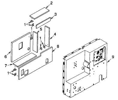
Figure 4-27. Front Panel Insulation
(13)
Drill out four rivets (Figure 4-26, 26) to remove identification plate (27).
(14)
Drill out four rivets (28) to remove slave receptacle plate (29)
(15)
Drill out four rivets (30), to remove flat washers (31), and operating instruction plate (32).
(16)
Peel off decals (33), (34), (35) and (36) to remove.
NOTE
The following procedure is typical for all instrument identification plates.
(17)
Remove two screws (37) and instrument identification plate (38).
c.
Assembly.
(1)
Fabricate insulation panels (Figure 4-27, 2 through 8), as required, per the following:
(a)
Cut insulation panel per appendix F.
NOTE
Paper backing on insulation panel must be removed when installed.
(b)
Carefully peel paper backing away from around insulation panel edge.
(c)
Cover exposed insulation panel edge with foil back tape (item 9, section II, appendix E) folded over
edges. Be sure tape is under paper backing on insulation panel.
4-81

