TM 5-4310-354-14
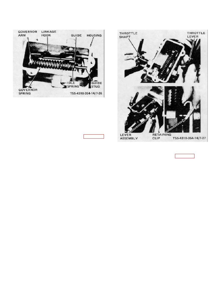
TS5-4310-354-14/7-26
Figure 7-26. Governor springs and hook, assembly.
NOTE
The apparent looseness of governor
parts is normal. Lost motion is taken
up when pump rotates.
(20) Assemble seal washer (28, figure 7-16)
TS5-4310-354-14/7-27
and shaft seal (29) on shaft (30).
Assemble shaft (30) partially through bore
Figure 7-27. Throttle shaft and lever, assembly
in housing. Slide throttle shaft lever (31)
over shaft so that projection in lever bore
(21) Assemble spacer (24, figure 7-16) to shaft
engages with keyway in shaft. Position
assembly (25) positioning with screw (23).
forked end of lever so that it straddles the
Assemble spacer arm (22), throttle lever
guide stud (32). If removed from shaft
assembly (21), spring (20), spring retainer
assembly (25), assemble nuts (27) and
(19), and secure to shaft assembly (25)
screws (26). Assemble seal washer (28)
with screw (18). Hook ends of spring (20)
and seal (29) on throttle shaft assembly
to lever (21) and arm (22). Install the
(25). Assemble throttle shaft assembly
washer (70) and screw (69).
(25) with slight rotary motion and firmly
seat the lever assembly (25) and shaft
(22) Lubricate shaft seals (114) with a light
(30). Locate and seat the retaining clip
mineral grease and slide into grooves of
(17). Throttle shaft and lever, assembly.
drive shaft (112). Seals must face in
opposite directions. Apply mineral grease
liberally around shaft between seals.
Assemble pilot tube seal (115). Note the
small off-center hole in tang of drive shaft.
This hole must coincide with similar hole
in distributor rotor when shaft is installed.
Carefully assemble drive shaft (112) into
housing until tang of shaft engages with
drive slot in distributor rotor. If removed
from shaft, place key (113) in shaft
keyway and tape until ready to assemble
injection pump to engine.
7-28


