TM 5-4310-354-14
(6) Carefully hold assembly together so rotor
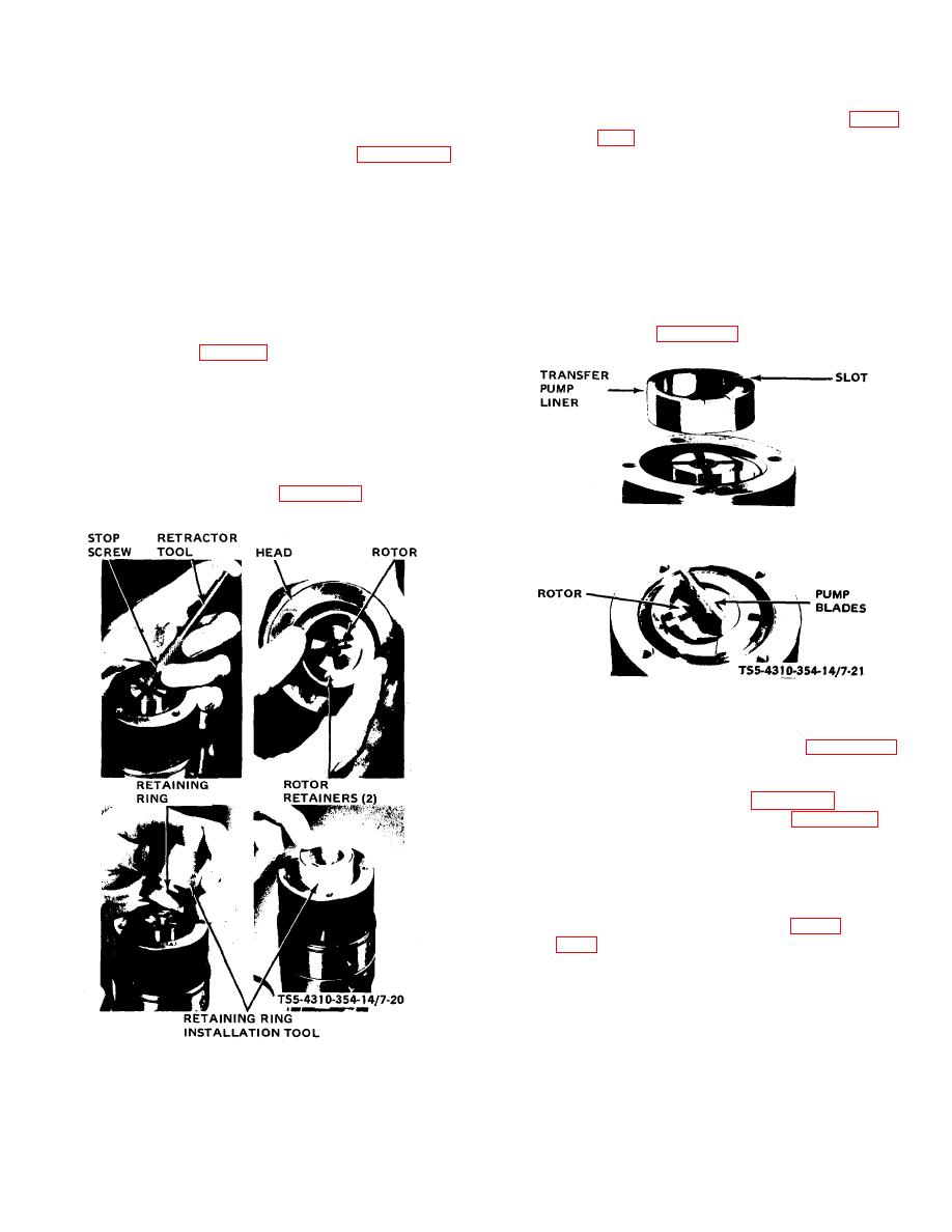
(8) Assemble transfer pump liner (91, figure
will not fall out and invert the entire unit so
that weight retainer (101, figure 7-16)
is in line with head locating screw hole
engages a bar on the holding fixture.
and the letter indicating correct pump
Assemble delivery valve (97) making
rotation faces upward.
certain it operates freely in bore.
Assemble delivery valve spring (96) and
(9) Carefully assemble transfer pump blade
delivery valve stop (95). The stop screw
springs (93) and blades (92) in slots of
(94) internal hex has one end which is
transfer pump rotor.
With one finger,
slightly relieved to clear delivery valve
rotate the liner (91) several times to check
stop (95). Make certain this relieved end
for binding; then, reposition liner to correct
of screw (94) faces down and assemble
position outlined in paragraph (8) above.
screw (94). With torque wrench, tighten
Refer to figure 7-21.
screw (table 1-1).
(7) Lift the hydraulic head slightly so that
inside face of the head is flush with rotor
end. Insert the two rotor retainers (99).
Position retainers (99) with outer sleeve of
Roosa Master Retaining Ring Installation
Tool, or equivalent, and install retaining
ring (98). Refer to figure 7-20.
TS5-4310-354-14/7-21
Figure 7-21. Transfer pump liner and blades, assembly.
(10) Assemble thrust plate (89, figure 7-16)
and seal (90). Mount end plate (77) so
that inlet is in line with metering valve (44)
bore. Locating pin (B, figure 7-22) will now
align with locating slot (A, figure 7-22) in
the transfer pump liner.
NOTE:
If locating pin and slot are 180 out of
alignment, check end plate (77, figure
with respect to pump rotation [C or
CC as marked on outside of end plate
(77) ].
TS5-4310-354-14/7-20
Figure 7-20. Delivery valve and rotor retainer, assembly.
7-25


