TM 5-4310-354-14
TS 5-4310-354-14/7-29
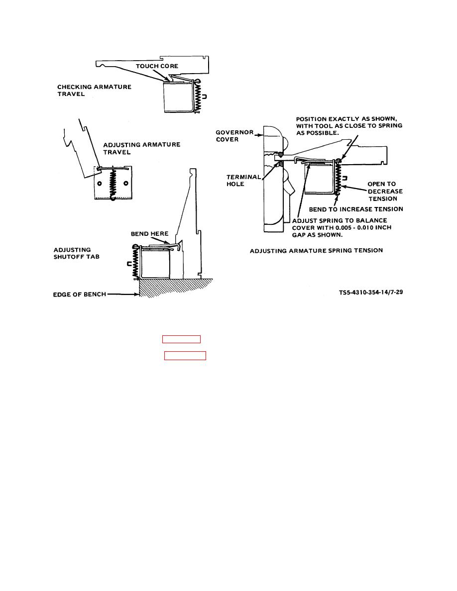
Figure 7-29. Armature and spring tension adjustment.
(b) Using same tool, adjust shutoff tab and
Assemble the two cover gaskets (118), timing
spring tension as shown in figure 7-29.
covers (117), and secure with screws (116). If
removed from housing, install identification plate
(25) Install new insulating tubes (13, igure 7-16) on
(120) with screws (119).
solenoid studs. Apply light coating of clean
mineral grease to the tubes (13) and assemble
e. Bench Testing.
After overhaul, prior to
solenoid assembly to cover (6).
Assemble
installation on the engine, the fuel injection pump should
insulating washers (11), contact washers (10),
be bench tested as follows:
contact nuts (9), and lock nuts (8) on solenoid
stud terminals. Install fuel return connector (5)
NOTE
into cover (6).
Using a new gasket (7),
assemble the cover assembly (6) to housing
All tests must be conducted using
(121) with three flat washers (4), lock washers
heated calibrating oil. Heat oil to
(3), and screws (2).
After testing and
110-115F (43 -46 C). Use 12SD12
adjustment, install wires and seals (1).
nozzles set to open at 2500 psi
2
(175.75 KG/CM ). Injection lines shall
(26) Assemble fuel line gaskets (110) and fuel line
be 3/32 inch (2.38 mm) inside
screws (109) finger tight until ready to install fuel
diameter, 20 inches (508 mm) long.
injection lines after pump is installed on engine.
Fresh, clean oil is necessary for
accurate testing and should be
changed as often as excessive foam
is noted.
7-30


