TM 5-4310-354-14
TS5-4310-354-14/7-18
TS5-4310-354-14/7-17
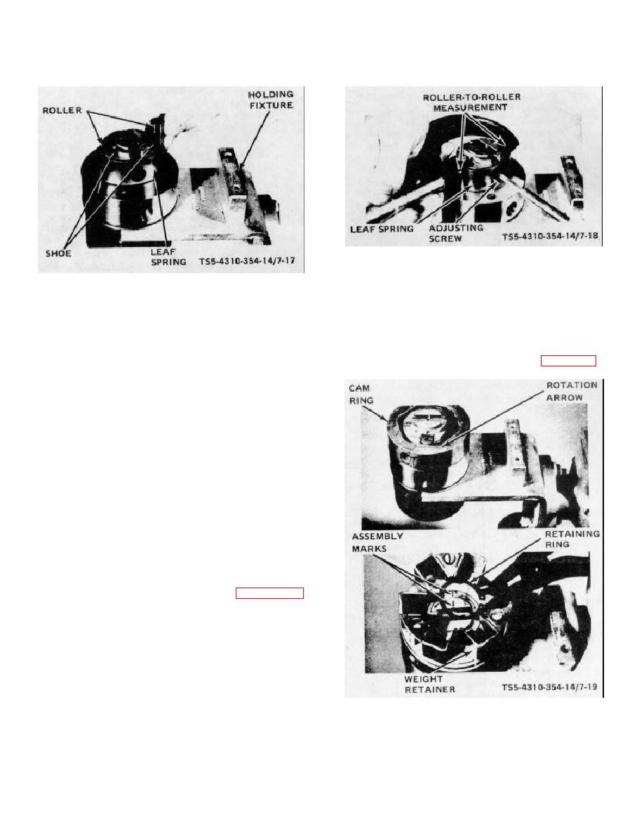
Figure 7-18. Roller-to-roller dimension setting.
(5) Place cam ring (102) on the hydraulic
Figure 7-17. Leaf spring, shoes, and rollers, assembly.
head with rotational direction arrow facing
upward. Place governor weight retainer
screw (103) to make adjusting easier.
(101) in position over the drive on the
Assemble screw (103) to hold leaf spring
distributor rotor.
Align the assembly
(104) but do not tighten at this point.
marks of weight retainer and rotor. Install
Assemble the cam roller shoes (106) and
retaining ring (100). Refer to figure 7-19.
cam rollers (105). Check for freedom of
movement.
Set the roller-to-roller
dimension as follows:
(a) By means of a suitable fitting to any one of
the hydraulic head outlets, apply clean,
dry air pressure of 30 to 100 psi (2.11 to
7.03 KG/CM2). Rotate the rotor until the
cam rollers (105) are pushed to their
extreme outward position by the air
pressure.
(b) Measure the roller-to-roller dimension
Proper setting of this dimension is
1.95555 to 1.9585 inches (49.6697 to
49.7469 mm).
(c) To set this dimension, use a socket
screwdriver and turn the leaf spring
adjusting screw (103, figure 7-16)
clockwise
to
increase
travel
and
counterclockwise to reduce travel. When
dimension is set, relieve air pressure and
remove air pressure fitting.
NOTE
TS5-4310-354-14/7-19
The
roller-to-roller
dimension
provides the accurate maximum fuel
Figure 7-19. Cam ring and weight retainer assembly.
setting and shall not be altered from
dimension given in step (b) above.
7-24


