TM 5-4310-354-14
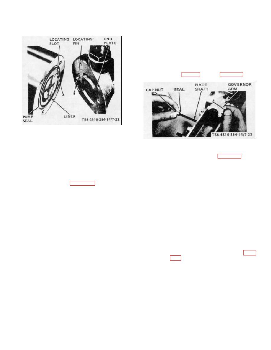
(13) Place governor arm (42) in position with
fork for governor linkage hook facing end
plate (77). Insert pivot shaft (41) (with
knife edge of shaft facing end plate)
through housing (121) bores and through
governor arm (42). Assemble the two
seals (40) and cap nuts (39). Torque nuts
(39) (table 1-1). Refer to figure 7-23.
TS5-4310-354-14/7-22
Figure 7-22. End plate, assembly.
TS5-4310-354-14/7-23
(11) Attach end plate (77) to hydraulic head
Figure 7-23. Governor arm, assembly.
and distributor assembly (111) with flat
washers (76), lock washers (75), and
(14) Install a new seal (108, figure 7-16) on the
screws (74).
hydraulic head (111). Apply a light film of
clean grease around the inside edge of
(12) Place hydraulic head and rotor assembly
the housing (121) bore to aid assembly.
(111), with drive end up, into open end of
Rotate cam ring (102) so that unthreaded
holding fixture. Place the six governor
hole in ring is in line with the metering
weights (72, figure 7-16) into sockets of
valve (44) bore in housing (121) to ensure
weight retainer (101) with weight slots
proper positioning of cam ring (102).
facing the assembly bore. Place governor
Grasp hydraulic head firmly with both
sleeve thrust washer (73) against thrust
hands and insert the assembly into
sleeve (71) with chamfered edge facing
housing bore with a slight rotary motion.
the sleeve. Hold the sleeve and thrust
Do not force. If assembly should cock
washer together with forefinger inserted
during insertion, withdraw and begin
through bore. Insert sleeve and thrust
assembly again. Make certain assembly is
washer into the slots of weights (72) by
positioned into housing past the hydraulic
tilting the weights back slightly. The tab
head seal (108). When assembled to this
on the thrust sleeve flange should face
position, rotate the hydraulic head until
upward. Sight across the tops of the
head locking screw holes in head and
assembled weights to make certain of
housing align. Assemble head locking
correct positioning. A weight higher than
screws (68) finger tight. Refer to figure
any other indicates incorrect assembly of
thrust washer (73).
7-26


