TM 5-4310-354-14
ensure freedom of movement.
Install
power piston seal (58), piston ring (57),
and plug (56).
(c) Install shims (66), insert outer spring (65)
and inner spring (64) into spring piston
(67). Install seals (63, 62) and plug (61).
(d) Install seal (48) and locating screw
assembly (47). Tighten screw (47) (table
(16) Turn pump and fixture upright in vise. Tighten
head locking screws (68) (table 1-1).
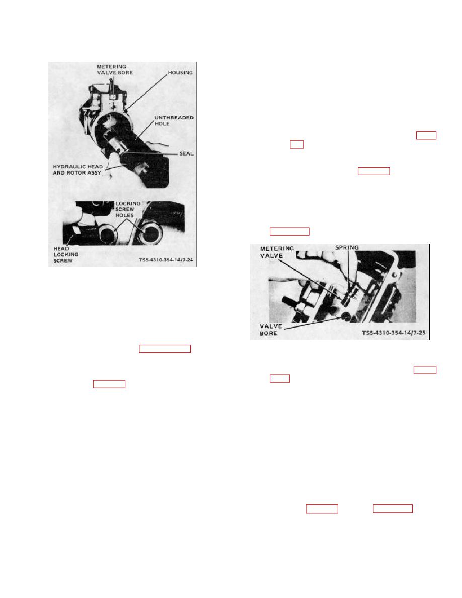
(17) Place metering valve spring (38) on metering
valve (44) and assemble valve into housing
bore. Depress and rotate the valve into housing
bore. Depress and rotate the valve several
times to ensure freedom of movement. Refer to
TS5-4310-354-14/7-24
Figure 7-24. Hydraulic head and rotor, assembly.
(15) Invert the pump and fixture in the
vise.
Assemble automatic advance as follows:
CAUTION
TS5-4310-354-14/7-25
Clockwise rotation pumps have
power piston (59, figure 7-16)
Figure 7-25. Metering valve and spring, assembly.
assembled on "C" side of pump.
(18) Pull back on governor linkage hook (43, figure
(a) Assemble and tighten cam advance screw
(55) (table 1-1). Install plug seal (54) and
correctly to the fork on governor arm (42).
plug (53).
Position opposite end of hook assembly over the
pin on the metering valve arm (46). Again check
(b) Rinse slide washers (60) and pistons (59,
for freedom of movement. Assemble metering
67) in clean oil. Stick washers (60) to
valve governor linkage spring (45).
power piston (59) and spring piston (67)
ends with clean grease.
Slide both
(19) On work bench, assemble governor spring (34),
pistons (59, 67) into bore, seating the slide
spring retainer (37), idling spring (36), and
washers (60) squarely on cam advance
spring guide (35). Pick up these parts between
screw (55). Make certain power piston
thumb and forefinger and engage spring (34)
(59) is assembled on correct side of
over tabs on governor arm (42). Insert guide
housing. Move pistons back and forth to
stud (32), with washer (33), through tapped hole
in housing (121) and into guide (35), spring (36),
retainer (37), and spring (34). Tighten guide
stud (32) (table 1-1). Refer to figure 7-26.
7-27


