TM 5-4310-354-14
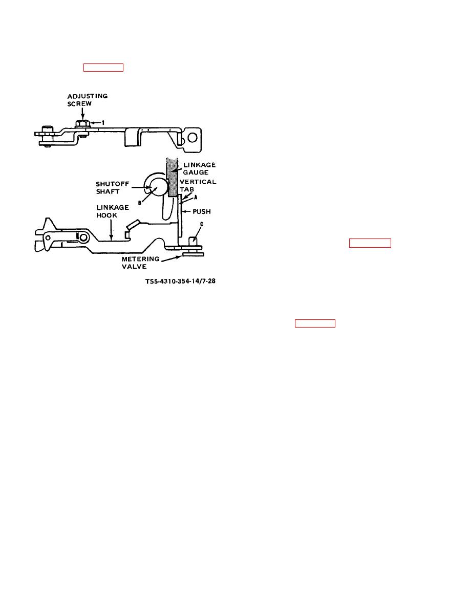
(23) Refer to figure 7-28 and adjust governor linkage,
shutoff shaft (B) and vertical tab (A) on
as necessary, in the following sequence:
linkage hook with linkage gauge, Roosa
Master No. 13389, or equivalent.
(b) With adjusting screw (1) tight, apply a
slight pressure to tab (A). At the same
time rotate pump one or two complete
revolutions by turning drive shaft to assure
that linkage is in full forward position.
Loosen adjusting screw (1) and slide
linkage to maximum open length.
(c) Insert Linkage Gauge between vertical tab
(A) and shutoff shaft (B). Slide linkage
hook together from rear until face of tab is
flush against gauge.
(d) Tighten adjusting screw (1).
Check
adjustment and reset if required.
(24) Assemble spring (15, figure 7-16), spring sleeve
(16), and arm assembly (14) to solenoid frame
(12). Before assembly of solenoid assembly to
the cover is made, adjust armature travel and
spring travel as follows:
TS 5-4310-354-14/7-28
(a) Using Roosa Master Tool No. 14067, or
equivalent, check and adjust armature
Figure 7-28. Linkage adjustment.
travel and spring tension as shown in
(a) Place throttle lever in wide open position
(and torque screw backed out) and check
clearance between rear of
7-29


