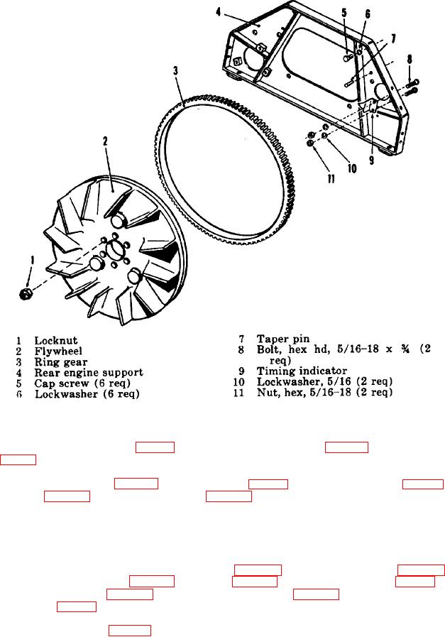
Figure 102. Exploded view of flywheel and rear support.
(3) Fasten the two braces (15, fig. 94) to the rear engine support (4, fig. 102) with two hex head bolts (14,
fig. 94), hex nuts (12) and lockwashers (13).
(4) Install the aftercooler (par. 117c), starting motor (par. 93b) and shutter air filter (par. 82e). Install the
housing (par. 130) and engine-compressor (par. 215).
222. Crankshaft and Main Bearings
a. Removal.
(1) Remove the engine-compressor from the truck (par. 214). Remove the housing (par. 128). Remove the
upper and lower oil pans (par. 217a), flywheel (par. 221a), and radiator and fan (par. 88a). Remove the
engine cylinder head (par. 122a) compressor cylinder head (par. 126a), and the pistons, connecting rods
and rings (par. 223a).
(2) Remove six cap screws (9, fig. 106) and the three outer bearing caps (10) with the lower main bearing
232

